Norge Style Washer Help
Maytag Performa & Atlantis plastic tub washers....
Norge, Magic Chef, American Admiral washers....
Always remember Electricity is dangerous and should be treated with respect.
Please pick a topic by Make and or problem...hope you find this helpful :-)
- Help for storing an appliance
- How a washer works, good to read this first
- How does the agitator come off my washer?
- Important Disclaimer
- My clothes have a whiting on them that looks like lint
- My washer makes a squeal noise when the spin stops
- My washer has a funky odor
- My washer motor runs but I get no agitation or spin
- Norge, Magic Chef, American Admiral washer + Performa and Atlantis style general information
- Noises
- Slow water fills
- Some new take apart pictures ( Maytag Performa & Atlantis...some take apart info )
- Replace the thrust bearing pulley kit help
- Washer Basics: Filling with water
- Washer sample wiring diagrams
- Washer belts: If your belt on any washer looks like this, replace the belt(s)
Maytag Performa & Atlantis plastic tub washers, Norge, Magic Chef, American Admiral washer:
This is a common way to gain access to an older style washer.
This is a common way for a newer style Performa and Atlantic style washer.
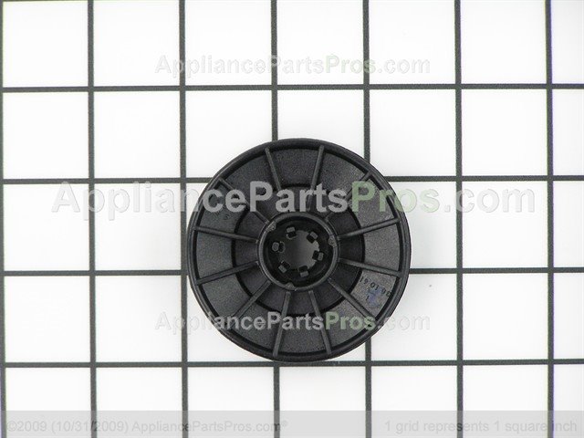
This is a belt driven washer. If your washer has a plastic main pulley ( transmission pulley and no spin solenoid ), the thrust bearing and pulley has had many troubles with burning and the bearings wearing out or rusting. This often makes the washer quit spinning, look for any burnt marks on the pulley or maybe eve none of the washers to be melted into the pulley. The pulley replacement is called a thrust bearing and pulley kit. The kit comes with the small washers, bearings, instructions and a new pulley. For a no spin and no draining problem, always check the lid switch first with a ohm meter.
The older style/design washer had a spin solenoid, the solenoid would be a good place to start for a no spin problem. You should be able to access the solenoid from the front panel. If one part of your washer quits, split your problem in 1/2....try to turn the belt by hand, either in agitation or spin to find out if it is capable to mechanically work, if yes, possible electrical problem (timer, switches, motor, etc). If washer still won't spin or agitate when you turn the belt by hand, possible mechanical problem (belt, transmission, pulleys, bearings, etc).
NOTE: The rotation directions, stated in this outline, view the component from its pulley end. The washer utilizes a reversible type motor which turns clockwise during the Agitate cycle and counter clockwise during the spin cycle. A single belt is used to transmit power from the motor pulley to the drive and pump pulleys. The transmission drive pulley, which drives the transmission drive shaft and hub assembly, and the pump pulley which drives the pump impeller, are in operation whenever the motor is running. The transmission assembly converts the power from the motor to either drive the agitator or spin the basket. The direction the clutch assembly rotates determines which action takes place.
When the drive pinion rotates in a clockwise direction, the gear lock mechanism exerts no force on the input pinion. When the input pinion starts to revolve counterclockwise the "wings" drop into dents in the lower housing preventing the pinion from turning.
DRIVE PULLEY AND CAMS
The drive pulley and cam is located below the brake assembly on the drive shaft.
All models are equipped with a plastic drive pulley which has the upper cam molded onto the bottom of the hub. The purpose of the pulley and cam arrangement is to drive
the clutch assembly during the agitate and spin cycle, and to disengage the brake assembly during the spin cycle.
The drive pulley slips over the drive shaft and rests against a series of washers, a thrust bearing, and a large washer type spacer. The spacer locates against the bottom of the
brake rotor and lining assembly.
The lower cam slips over the end of the drive shaft where splines formed in the cam engage with mating splines on the drive shaft end. This imparts a direct drive from the cam
to the drive shaft. A shoulder molded on the bottom of the
pulley hub engages "dogs" formed on the sides of the lower cam, and will drive it and the drive shaft in either direction.
A washer and retaining ring secure the pulley and cam on the drive shaft. A plastic dust cap snaps to the underside of the pulley to keep the cam surfaces clean.
OPERATION: AGITATION
When the drive pulley rotates CLOCKWISE, the upper and lower cams are designed to nest together which allows the drive pulley to remain in position on the drive shaft. The break
remains engaged and the drive pulley will turn the lower cam and drive the shaft to cause the transmission to agitate.
The agitation is due to the clockwise (agitate) rotation of the drive shaft and the hub assembly as it is transmitted to the input pinion by the clutch spring. The input pinion meshes
with the dual cluster gears which, in turn mesh with the dual crank gears (Figure 2-3). The circular motion of the dual crank gears are converted to the oscillating action of the agitator shaft by the dual rack gears. The rack gears have a stud that drops into the crank gears. These rack gears are contained by a rack carrier. Any tendency of the transmission to turn, or "creep," is prevented by the engaged brake
assembly located on the under side of the suspension
housing.
OPERATION: SPIN
When the drive pulley rotates COUNTER CLOCKWISE, the upper cam and pulley ride up the lower cam approximately 3/16 of an inch before the driving shoulders on the pulley
hub engage the "dogs" on the lower cam. This causes the top of the pulley hub to push against the spacer which compresses the brake spring and lifts the brake rotor and lining
assembly off the brake stator. The brake is disengaged and the pulley will turn the lower cam and drive shaft to cause the transmission to spin. A nylon cam, along with a special drive pulley, provides a cam action which raises the drive pulley during the counterclockwise (spin) rotation of the motor. As
the drive pulley hub moves up, it compresses a brake spring and lifts the brake rotor and lining assembly, disengaging it from the stator. The transmission is now free to spin.
The counter clockwise rotation of the drive shaft and hub assembly causes the clutch spring to relax into an override position. The clutch spring still exerts a driving force to the
input pinion even when it is in the override position. As this driving force of torque starts to turn the input pinion in a counter clockwise direction, it causes the "wings" of the gear lock mechanism to drop into dents on the lower housing. This prevents the input pinion from revolving in the counterclockwise direction. Therefore, the torque being delivered by the clutch spring is exerted against the transmission housing, causing the entire assembly to
rotate. The washer basket is mounted to the basket drive hub which is secured to the transmission cover assembly, and revolves as part of the transmission. In this direction, the
pump assembly will drain the water out of the unit.
The brake assembly is located inside the domed area of the suspension housing and consists of the following components: brake spring retainer, brake spring, rotor and lining assembly and the brake stator. The brake assembly, as well as the snubber, is held in position by the brake stator which is
secured to the underside of the suspension housing by six mounting screws. Spring pressure forces the rotor and lining
assembly down on the brake stator and prevents the transmission from turning during agitation. As stated previously, the drive pulley and cams provide a cam action which raises the drive pulley during the counter clockwise
(spin) direction of the motor. When the drive pulley hub travels upward, it compresses the brake spring and moves the rotor and lining assembly up the drive tube disengaging it from the stator. The transmission is now free to spin.
Splines in the brake rotor hub mesh with splines on the drive tube end to provide positive vertical movement for the rotor and lining assembly. The splines are greased for ease of movement.
CAUTION:
The brake assembly has a compressive spring force of approximately 200 pounds.
So your Maytag Atlantis or Performa washer finishes spinning the water out of your clothes and then squeals very loudly.
The problem is the brake. The odd time what happens is moisture gets on the brake rotor and the squealing is heard when the brake stator is applied to stop the tub from spinning. This moisture, may drip down from the tub onto the brake rotor which could indicate a leaky tub seal. If you can't see any dripping when you fill the tub with water, don't worry about the tub seal. Many times than not the brake is just going sour on it's own.
Sometimes you can fix the squealing by cleaning the rotor and stator with a light sandpaper, such as emery/sand cloth. If that doesn't work you will need to replace the brake stator and rotor. If you need to replace them replace both parts together, don't just change the stator without also replacing the rotor, or vice versa. And here's a bonus tip: the brake spring exerts 200 pounds of force. If you try to remove the six 5/16" screws without using this brake removal tool, serious injury can/could happen!! The splined part in the middle of the brake needs to be greased really good before putting the brake back on!
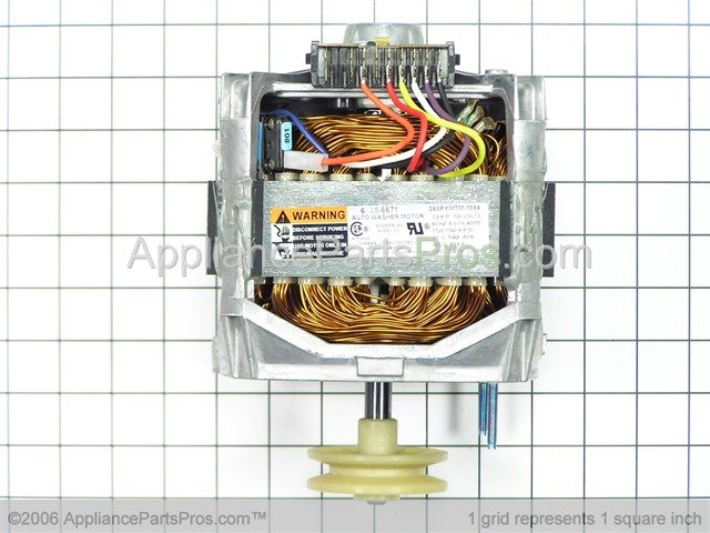
The drive/motor pulley on these washers is plastic. It can wear and start to slip on the drive belt, might be best to replace the belt at the same time if you find a worn/ground up motor pulley. The motor pulley presses onto the motor shaft, cutting or breaking the old one is common when changing it.
The drain pump assembly seem to be a common noise maker for this style of an washer. Sometimes something is just caught or jammed inside the drain pump, many times the pump has to be changed because of an noise or seizing up problem.
Related Links


